IoT Pentesting Basics: Root Shell via UART Exploitation


Every IoT pentest starts with opening up the device. When this happens we can start to think like the developers of the system. What things did they use for debugging when building the system? Could any of those debug interfaces be left behind? Still enabled?
This post walks through the process of identifying and exploiting a UART interface on a real IoT device.
The Target Device

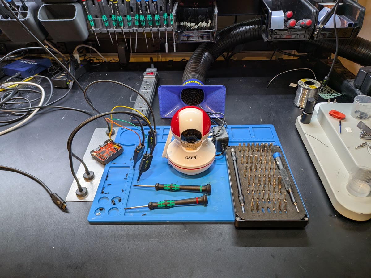
The device under test is the Chinese-produced Oker G955v1, a WiFi-enabled IP camera. This model is not available in US markets. I acquired it during my time in Southeast Asia.
Device Teardown
Physical access to the PCB is the first step in any hardware security assessment. For the Oker G955v1, the teardown process was straightforward:
- Removed 4 screws from the bottom of the camera housing
- Carefully separated the two halves of the plastic shell
- Located the main PCB mounted inside the camera dome
- Removed 2 additional screws securing the PCB to the plastic housing
- Extracted the PCB for analysis
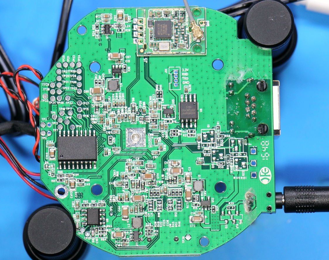
The teardown revealed a main PCB with several unpopulated headers, a promising sign for hardware hackers looking for debug interfaces.
Finding UART
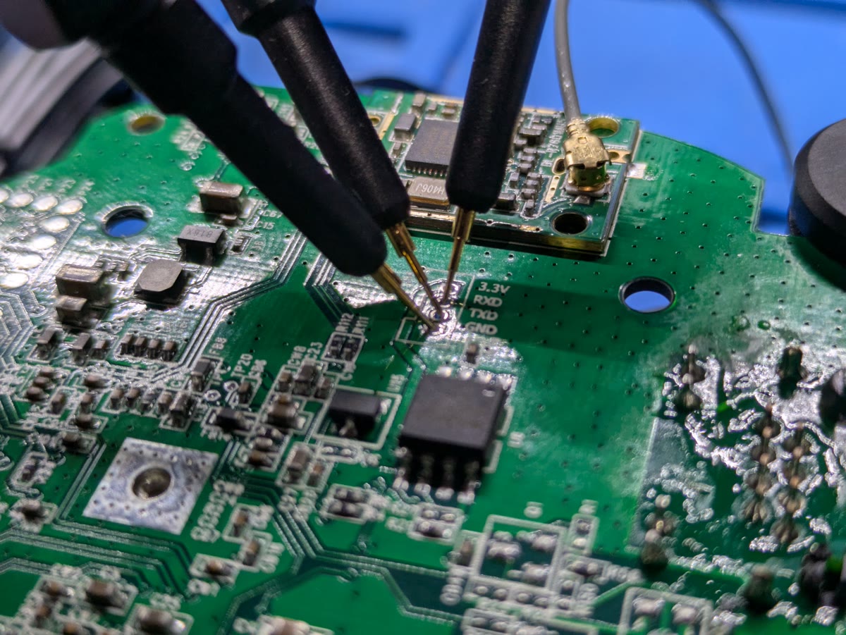
Unlike many IoT devices where UART pins must be identified through testing and reverse engineering, the Oker G955v1 made things easy. The UART interface was clearly labeled on an unpopulated 4-pin header on the main PCB:
- 3v3 (Power)
- TXD (Transmit)
- RXD (Receive)
- GND (Ground)
To connect to the UART interface, I used:
- Tigard multi-protocol tool - a versatile hardware hacking interface
- 3 PCBite probes - probes that make temporary connections to PCB pads
I connected the Tigard's UART pins to the corresponding pins on the camera (TXD to RXD, RXD to TXD, GND to GND), leaving the 3v3 pin disconnected since the device would be externally powered.
With the hardware connected, I opened a terminal emulator using picocom:
picocom -b 115200 /dev/ttyUSB0
The baud rate of 115200 is the most common default for embedded Linux devices, which is why it was my first guess. In cases where 115200 doesn't work, other common rates to try include 9600, 38400, and 57600.
Observing Boot Messages
With the terminal emulator running, I powered on the IP camera. Immediately, boot messages began streaming to the console:
U-Boot identification and prompt to pause bootloader:
U-Boot 2013.01 (Jan 09 2015 - 14:10:09)

I2C:   ready
DRAM:  64 MiB
ROM CODE has enable I cache
SPI mode
SF: Got idcodes
00000000: ef 40 18 00    .@..
SF: Detected W25Q128 with page size 64 KiB, total 16 MiB
flash is 3byte mode
In:    serial
Out:   serial
Err:   serial
...
Hit any key to stop autoboot:  0
Kernel command line:
Kernel command line: mem=128M gmmem=90M console=ttyS0,115200 user_debug=31 init=/squashfs_init root=/dev/mtdblock2 rootfstype=squashfs
Partition layout:
SPI_FLASH spi0.0: w25q128bv (16384 Kbytes)
Creating 5 MTD partitions on "nor-flash":
0x000000010000-0x000000060000 : "UBOOT"
0x000000060000-0x000000300000 : "LINUX"
0x000000300000-0x000000f00000 : "FS"
0x000000f00000-0x000001000000 : "USER0"
0x000000000000-0x000001000000 : "ALL"
The boot sequence revealed critical information about the device's firmware architecture, including the bootloader version, kernel parameters, and filesystem layout. But the most interesting message appeared during the boot process:
Press q -> ENTER to exit boot procedure?
This message indicated an opportunity to interrupt the normal boot sequence.
Dropping to Root
I pressed q followed by ENTER as instructed by the boot message. The device immediately stopped the boot process and dropped into a root shell:
   Press q -> ENTER to exit boot procedure? / #
/ #
/ # whoami
root
No password required. No authentication mechanism. Direct root access to the device's Linux filesystem.
From this root shell, I had full control over the device. I could:
- Read all files on the filesystem
- Extract firmware for analysis
- Modify system configurations
- Observe running processes
- Analyze network configurations
One fun finding was a hardcoded password hash:
/ # cat /etc/shadow
root:$6$Iw0BJ8Hu$CtZloGU0BVPpTmiwEZlDzPOvqVKuxTl.EbVjuOUGfAOmUz3kdyZ6J9ilw1FYPfZILvjS617iAJNdsOUontUBm.:16665:0:99999:7:::
bin:*:12963:0:99999:7:::
daemon:*:12963:0:99999:7:::
adm:*:12963:0:99999:7:::
lp:*:12963:0:99999:7:::
sync:*:12963:0:99999:7:::
shutdown:*:12963:0:99999:7:::
halt:*:12963:0:99999:7:::
uucp:*:12963:0:99999:7:::
operator:*:12963:0:99999:7:::
nobody:*:12963:0:99999:7:::
This root password can't be changed by the user of the device because the /etc/shadow file is stored in a squashfs filesystem, which is read-only by design.
Summary
The Oker G955v1 demonstrates a common vulnerability pattern in IoT devices: an easily accessible UART interface with no authentication protecting root access.
Need IoT Security Expertise?
Brown Fine Security provides expert IoT penetration testing to help secure your connected devices. From hardware analysis to cloud API testing, we uncover vulnerabilities before attackers do.
Get a Free ConsultationWant to Learn IoT Hacking?
Ready to break into IoT security? Our hands-on training courses teach real-world hardware hacking, firmware analysis, and IoT exploitation techniques used by professional pentesters.
Explore Training Courses